An external lighted push button can be added to turn the radar on and off. A connector for this is included on the Payload Divider PCB.
Button choices
The intended button for the UAV version is HB15CKW01-5C-CB.
Most other similar buttons can be used. For the ground-based version, we use ULV4F2BSS311. Some of the photos on this page are taken with this button, which can be mounted externally.
Wiring the button
The button connector is a 5 position JST GH connector. The connectors and pre-crimped wires are available separately or you can buy a kit.
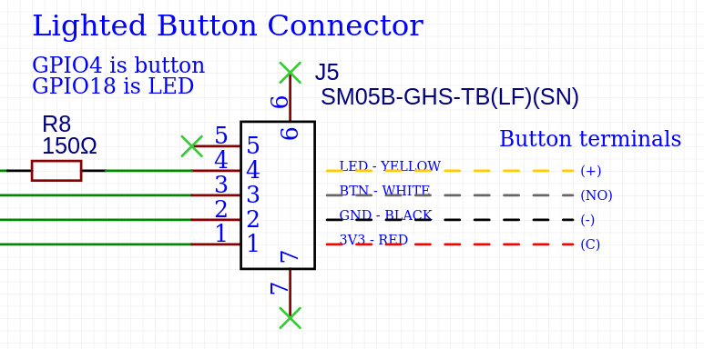
Schematic section for the button connector. Right side shows recommended connections to the lighted button.
If you buy pre-crimped wires, you’ll need to cut the connector on one side off.
For JST connectors, the small notch on the contact aligns with the bottom side of the connector. On the bottom of the connector housing, there are a series of small plastic pins that will raise up as you insert the contact. Once you get the contact fully inserted, this pin will fall back down to lay flush.
To assemble the button:
- Cut pre-crimped JST wires to length
- Following the image above, strip and solder the free end of each wire to the specified terminals on the switch.
- Place a piece of heatshrink over each terminal and shrink.
- (Optional) Twist the wires gently and use small pieces of heat shrink to keep them in a neat bundle.
- Insert the contacts into the JST GH 5 position housing, following the diagram above.
- Mount the button and insert the connector into the plug on the payload divider PCB.
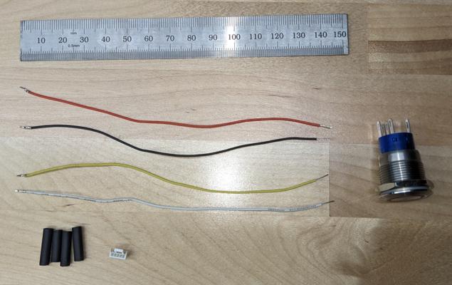
Components of the button assembly. Note that these pictures were taken with the alternative version of the button designed to be mounted on the outside of a Pelican case.
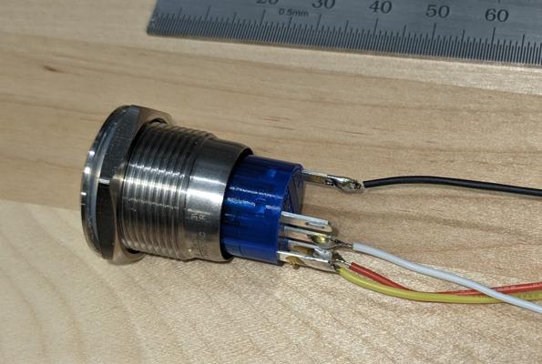
Cables soldered to the terminals of the button