5V Power Board and Power Harnesses
Build instructions for 5V power system
5V Power Harness
All lengths are tip to tip (including any connectors)
Connector side 1: Female M8 connector (McMaster Part #8605N11)
M8 pinout:
- Brown wire: 5V
- Blue wire: GND
Cut brown wire ~0.5 cm shorter than blue
Connector side 2: Molex Micro-Fit 3.0 3 Pos connector (Molex Part #0436450300)
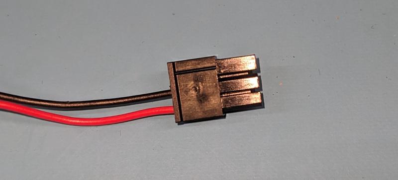
Molex Micro-Fit 3 Position (5V Power) pinout – note location of the line indicating pin 1
Molex Micro-Fit pinout:
- Pin 1: unused
- Pin 2: GND (black)
- Pin 3: 5V (red)
Use 22 AWG female terminals
Pre-crimped wires are available. Molex part is 2147611201 (black) and 2147612201 (red)
Cut black ~0.5 cm shorter than red
Assembly instructions
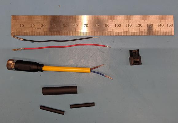
Components of 5V power harness
- Cut all wires as shown in the photo above
- Solder M8 brown wire to red Micro-Fit
- Solder M8 blue wire to black Micro-Fit
- Heat shrink each individual connection
- Place larger (glue lined, if available) heat shrink over both connections and extending onto the yellow sheath of the M8 cable
- Insert female MicroFit terminals into 3 position connector
Result should look like below:
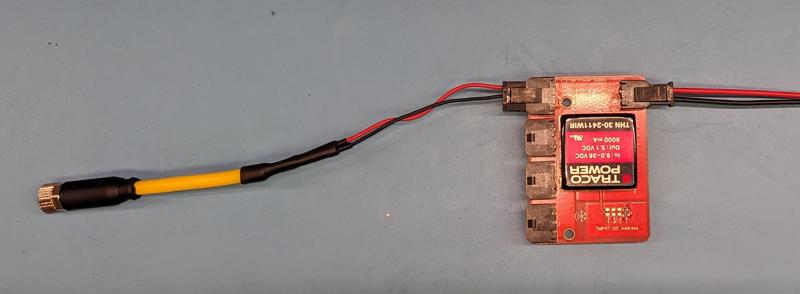
Completed 5V power harness (on left) connected to 5V power board