This is the multi-page printable view of this section. Click here to print.
Radar Code
1 - Compatible hardware
Selecting a Software-Defined Radio (SDR)
ORCA is built upon the USRP Hardware Driver (UHD). As such, it is theoretically compatible with any Ettus SDR. We have primarily tested with B and X series devices (B205mini and X310, in particular), however most other Ettus SDRs should work with minor tweaks.
The basic capabilities of the two models we regularly use are detailed below:
| SDR | Frequency Range (GHz) | Bandwidth (MHz) | Channels | Mass (kg) | Approximate Cost (USD) |
|---|---|---|---|---|---|
| X310 with UBX160 | 0.01-6 | 200 | 2 TX, 2 RX | 1.7 | $14,0000 |
| B205mini-i | 0.07-6 | 56 | 1 TX, 1 RX | 0.024 | $1,600 |
In general, we recommend B series devices for applications with constraints on size, weight, power, or budget. When capabilities beyond the B series are needed, we recommend the X series.
If no device in either series suits your needs, consider other Ettus SDRs. Most should work with minor tweaks. The exception to note are E series devices, which include an embedded computer running Linux. In theory, this code could be run on that embedded computer, however the performance limitations would limit the use cases.
Host Computer
Unless you choose an E series device (see caution above), you will also need a computer to interface with the SDR. This computer is where the ORCA code will run.
The capabilities of the computer can make a significant difference in the system performance. The host computer must support an interface with enough bandwidth for the samples you want to transfer and be able to store these samples to an appropriate storage medium.
If you’re not resource constrained, a modern laptop will provide more than enough processing power, as long as it supports the interface you need. Keep in mind that X-series SDRs need a 10 gigabit ethernet (10 GigE) interface to achieve maximum sample rates. Few laptops natively support 10 GigE, however there are Thunderbolt adapters available. (Not all USB C ports support Thunderbolt and it may not be available on low-end laptops.)
For an embedded solution, Raspberry Pi’s are suitable for working with B series devices. The performance of the Raspberry Pi 5 greatly exceeds the Raspberry Pi 4, likely due to the introduction of a new USB interface chip.
Some caution is advised with other single-board computers. Their performance will likely be limited by their choice of USB controller chip.
For some examples of duty cycles achievable with various combinations of SDRs and host computers, see the figure below. Note that actual performance will depend on a variety of factors, including your exact configuration and the speed of your storage medium.

Example results from running error_code_late_command_sweep.py on several
combinations of host computers and SDRs.
2 - Code overview
Conda environment setup
All of the required dependencies can be installed as a conda environment using
the environment.yaml file in the repository. More instructions can be found
in the README
file.
Startup scripts
The X series devices require some initial network configuration. For convenience, a startup script is provided to automate this setup. You may need to tweak this file to your setup.
Runner scripts
The basic steps required to run the radar are:
- Build the C++ code
- Generate a chirp file to transmit based on your configuration
- Run the compiled radar code
- Move the collected data to an appropriate location
The main interface for running the radar code is through run.py, a Python
script designed to automate the above process. This script is run as follows:
python run.py config/my_radar_configuration.yaml
At the end of the data collection, data will be saved with the current date to a location specified in the YAML config file.
Generally, three files are saved:
YYYYMMDD_hhmmss_rx_samps.bin- This is a binary file containing the raw samples recorded the SDR. Note that this file is not interpretable unless you also have the config file used.YYYYMMDD_hhmmss_config.yaml- This is the YAML config file passed torun.py. It defines all parameters of the data collection, allowing for therx_samps.binfile to be interpreted and processed.YYYYMMDD_hhmmss_uhd_stdout.log- This is a text file containing the output of running the radar code. This is helpful for debugging and also contains a log of any errors encountered, which may be required to reconstruct the timing of each recording.
More details on the files stored and how these can be re-processed into a Zarr file are on the file formats page.
Note that there are also settings available to break rx_samps.bin into multiple
files as needed.
SDR interface code
For performance reasons, the code directly interfacing with the SDR is written
in C++. This code is all located in the sdr/ directory of the repository.
The main radar code is contained in main.cpp (with some SDR setup code located
in rf_settings.cpp). The radar code runs in two threads, as shown in the
figure below.
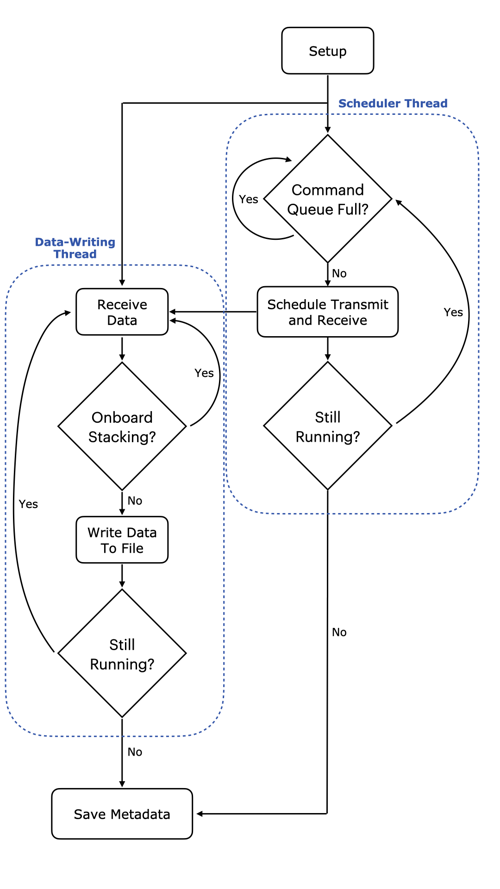
General architecture of the ORCA code
One thread is responsible for scheduling timed commands that are enqueued into FIFO queues within the SDR’s FPGA.
The other thead is responsible for pulling received samples from the SDR and writing them to a file on the host computer.
For a more complete overview, please refer to our paper:
T. O. Teisberg, A. L. Broome and D. M. Schroeder, “Open Radar Code Architecture (ORCA): A Platform for Software-Defined Coherent Chirped Radar Systems,” in IEEE Transactions on Geoscience and Remote Sensing, vol. 62, pp. 1-11, 2024, Art no. 5109411, doi: 10.1109/TGRS.2024.3446368.
3 - Configuration options
config.yamlThe entire configuration that controls the radar is defined in a single configuration file. This file is provided at runtime to run.py and encapsulates all of the settings needed to run various experiments on different hardware setups. Configuration files are specified in the YAML format and contained in the config/ folder of the ORCA repository. Default configuration files are included to run the code on a B205mini-i (default_b205.yaml1) and on an X310 (default_x310.yaml). Here we explain the basics behind the settings available to the user via the config file.
Chirp and Pulse Parameters
sample_rate: Sample rate of the generated chirp (used as TX and RX rate too), specified in Hz- On the X310, the sample rate should be an even integer division of the main clock rate
chirp_type: Chirp frequency progression type- Supported options: “linear”, “hyperbolic”
chirp_bandwidth: Bandwidth of the chirp, specified in Hz- Should be less than or equal to
sample_rateto satisfy Nyquist
- Should be less than or equal to
lo_offset_sw: Center frequency of the chirp, relative toRF0:freq(the RF center frequency), specified in Hzwindow: Window function applied to the chirp- Supported options: “rectangular”, “hamming”, “blackman”, “kaiser10”, “kaiser14”, “kaiser18”
- Applied on transmit and receive by default
chirp_length: Chirp length without zero padding, specified in secondspulse_length: Total pulse length (chirp + symmetric zero padding), specified in seconds- set equal to
chirp_lengthif no zero padding is desired
- set equal to
out_file: Name of the output binary file containing pulse samplesshow_plot: Whether to display a time-domain plot of the generated chirp (True or False)
Device Connection and Data Transfer Parameters
device_args: USRP device arguments are used to identify specific SDRs (if multiple areconnected to the same computer), to configure model-specific parameters, and to set transport parameters of the link (USB, ethernet) between the SDR and the host computer.- See the default config file or Ettus UHD examples for the SDR you wish to use to set appropriately
subdev: Active SDR submodules- See the default config file or Ettus UHD examples for the SDR you wish to use to set appropriately
clk_ref: SDR clock reference source- Supported options: “internal”, “external”, “gpsdo”
- “external” requires an external clock reference connected to the SDR
- “gpsdo” requires a GPSDO module to be installed on the SDR
clk_rate: SDR main clock frequency, specified in Hz- only specific frequencies are allowable for each SDR, see Ettus documentation for more information
tx_channels: list of TX channels to use (comma separated)rx_channels: list of RX channels to use (comma separated)cpu_format: CPU-side sample format- Supported options: “fc32”, “sc16”, “sc8”
otw_format: On the wire format- any format supported
GPIO Configuration Parameters
Many of the Ettus SDRs have GPIO pins which can be used for conveying automatic transmit/receive signals or other general signals to external devices. The parameters in this section are specific to how MAPPERR and PEREGRINE use the SDR GPIO and can be adapted for other use cases.
gpio_bank: Which GPIO bank to use- “FP0” is the front panel and default bank on the X310
pwr_amp_pin: Which GPIO pin to use fo external power amplifier control- set to “-1” if not using
ref_out: Turns the 10 MHz reference out signal on the X310 on (1) or off (0)- set to (-1) if the SDR does not support a 10 MHz reference out signal
RF Frontend 0 Configuration Parameters
RF configuration parameters for a single-channel radar setup.
rx_rate: RX sample rate, specified in Hz- defaults to be equal to
sample_rate
- defaults to be equal to
tx_rate: TX sample rate, specified in Hz- defaults to be equal to
sample_rate
- defaults to be equal to
freq: Center frequency (LO/mixer frequency), specified in Hzlo_offset: hardware LO/mixer offset, specified in Hzrx_gain: RX gain, specified in dB- available gain range dependent on specific SDR
tx_gain: TX gain, specified in dB- available gain range dependent on specific SDR
bw: Configurable hardware filter bandwidth, specified in Hz- not supported on all SDRs
- set to 0 if not supported
tx_ant: Port to be used for TXrx_ant: Port to be used for RXtransmit: Whether to transmit data samples or not- set to “true” (or leave blank) to transmit samples (normal operation)
- set to “false” to completely disable transmit
tuning_args: Set integer-N or fractional tuning arguments- only supported on some SDRs
- leave as "" to do nothing
RF Frontend 1 Configuration Parameters
RF configuration parameters for the second channel of a multi-channel radar setup. This is only supported on SDRs with more than 2 TX/RX ports. Parameters are the same as in RF Frontend 0 Configuration.
Pulse Timing Parameters
time_offset: Offset time after set up before the first received sample, specified in secondstx_duration: Transmission duration, specified in seconds- defaults as, and should be, equal to
pulse_length
- defaults as, and should be, equal to
rx_duration: Receive duration, specified in seconds- should be long enough to capture echoes from the expected most distant target
pulse_rep_int: pulse repetition interval, specified in seconds- should be longer than or equal to
rx_duration
- should be longer than or equal to
error_recovery_time: Additional time added (on top ofpulse_rep_int) to the next scheduled set of commands after an error occurs.- Most errors are due to a command being enqueued too late, so providing some extra buffer time lets the host computer “catch up”
tx_lead: Time between start of TX and RX, specified in seconds- can be used for psuedo-blanking
num_pulses: Number of chirps/pulses to transmit and receive- set to -1 to continuously transmit and record until stopped by CTRL-C
- code will record
num_pulsesof error-free pulses before terminating
num_presums: Number of received pulses to coherently average before writing to filephase_dithering: Whether to enable phase dithering or not
During Recording File Location Parameters
chirp_loc: Which chirp file to transmit- in most cases, should be the same as
out_file
- in most cases, should be the same as
save_loc: (Temporary) location to write received samples togps_loc: (Temporary) location to save GPS data- only works if “gpsdo” is selected for
clk_ref
- only works if “gpsdo” is selected for
max_chirps_per_file: Maximum number of chirps (after presumming) to write to a single file- set to -1 to avoid breaking into multiple files
File Save Locations for run.py
These settings are only used by run.py, they are not read by main.cpp.
final_save_loc: Save location for the big final file, set tonullif you don’t want to save a big file- if
max_chirps_per_file-= -1 (i.e. all data will be written directly to a single file), then final_save_loc and save_partial_files will be ignored
- if
save_partial_files: Set to True if you want individual small files to be copied with the timestamp, set to False if you just want the big merged file to be copied with the timestamp- if
max_chirps_per_file== -1 (i.e. all data will be written directly to a single file), then final_save_loc and save_partial_files will be ignored
- if
save_gps: Set to True if using GPS and wanting to save GPS location data, set to False otherwise
4 - Host computer transport parameter tuning
The maximum duty cycle you can achieve is a function of the SDR you use, the host computer, and the bandwidth you need. This page outlines suggestions for how to figure out an achievable duty cycle and what parameters can be tweaked to maximize this.
General process for benchmarking duty cycle
Determine the maximum achievable bandwidth with benchmark_rate
Use the USRP example benchmark_rate program (located at
<path to conda install>/envs/<uhd environment name>/lib/uhd/examples) to
determine the approximate maximum duty cycle you can achieve. For instance, with
a Pi 4 and b205mini, I can reach about a 25% duty cycle – defined as sample
rate divided by desired sample rate (14 Msps / 56 Msps in this case) – while
consistently getting 0 dropped packets.
./benchmark_rate --tx_rate 14e6 --rx_rate 14e6 --tx_otw sc12 --rx_otw sc12 --args="num_recv_frames=512,num_send_frames=512,recv_frame_size=16000,send_frame_size=16000"
This is also the stage to experiment with what transport parameters allow for the highest throughput on your combination of computer/interface/SDR. However the choice of (send/recv)_frame_size should be based on the number of samples per chirp and won’t have the same kind of impact in this continuous streaming case. In other words, you can get close but more tweaking later will help – probably.
Read about USB transport parameters on the Ettus website.
Figure out desired pulse lengths (RX and TX) and set frame sizes appropriately
Basically you want one full set of received samples to fit in a frame. See many more details about this in “Transport layer - throughput limitations” below.
Run tests/error_code_late_command_sweep.py to figure out your max duty cycle
This will sweep across effective duty cycles from 100% to 1, testing the
equivalent pulse_rep_int for each one. The script produces a plot (saved as
error_code_late_command.png) that shows percent of errors versus duty cycle.
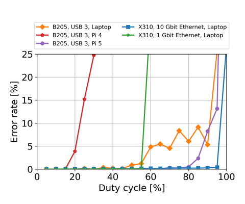
Example results from running error_code_late_command_sweep.py on several
combinations of host computers and SDRs.
Tuning transport parameters
In addition to getting late commands, the other issues we can run into are overflows (D on network-based devices, O on other devices) and underflows (U on all devices). There are also sequence errors (S) that often go along with late commands (L). Overflows mean that the buffers filled up and samples from the SDR are not being consumed fast enough. Underflows mean that the SDR did not receive samples to transmit before it needed to transmit those samples.
The Ettus knowledge base has a page detailing theoretical maximum transfer rates for each device.
Depending on the device, data is transferred over USB using libUSB, GigE, 10GigE, or PCI-E. For each option, there are various tunable parameters that impact the packet sizes and buffers used.
For libUSB, the transport parameters are:
(send/recv)_frame_size is the maximum packet payload size in bytes. The
maximum number of samples that fits into a packet is <packet size in bytes>/<bytes per sample>.
The bytes per sample is determined by the over-the-wire format
(see otw_format).
For example, sc12 requires 24 bit/samples, which is 3 bytes. It’s named sc12
because each value is 12 bits, but there are two values per samples (I, Q).
You can query the max number of samples based on your selected
(send/recv)_frame_size through the TX or RX streamers:
tx_stream->get_max_num_samps() or rx_stream->get_max_num_samps()
The default is around 8 MB (on my laptop and on the Pi 4B, both running Ubuntu-derived variants). If you set it too high, you’ll get an error message.
In most cases one full chirp (TX) or the received samples associated with one full chirp should fit and a good choice is to set the frame sizes to be equal to (or just barely larger than) the expected number of TX and RX samples, respectively, per chirp.
num_(send/recv)_frames controls how many buffers of size
(send/recv)_frame_size are created. The more buffers you allocate for
receiving, the longer your host program can lag for before causing an overflow.
LibUSB will give you a memory error if you try to allocate too much memory overall (roughly frame size * number of frames).
This is also why you don’t want arbitrarily large frame sizes. You end up wasting RAM if you’re allocating buffers that are longer than the maximum packet size you expect.
num_recv_frames is one of the most commonly talked about points on the USRP
mailing list for throughput issues on the b2xx devices. Apparently the default
value is very small (though I wasn’t able to figure out how to find the actual
default).
You set these parameters in the device arguments string. For us, that means something like this in the config YAML:
device_args: "num_recv_frames=700,num_send_frames=700,recv_frame_size=11000,send_frame_size=11000"
As described above, the USRP example program benchmark_rate is very useful for playing with these parameters quickly and figuring out what the limits are.
The host side matters a lot here too. The amount of RAM available on the host
directly limits the num_(send/recv)_frames. Processing speed of the host in
general can easily be the bottleneck. Finally, some USB 3.0 controllers are
known to work better than others. The Ettus knowledge base used to have a table
of performance on a few selected USB controllers. An archive of that page is
available here.
(The Pi 4 uses a VL805 controller. The Pi 5 has a new USB controller that performs far better.)